Skip to content

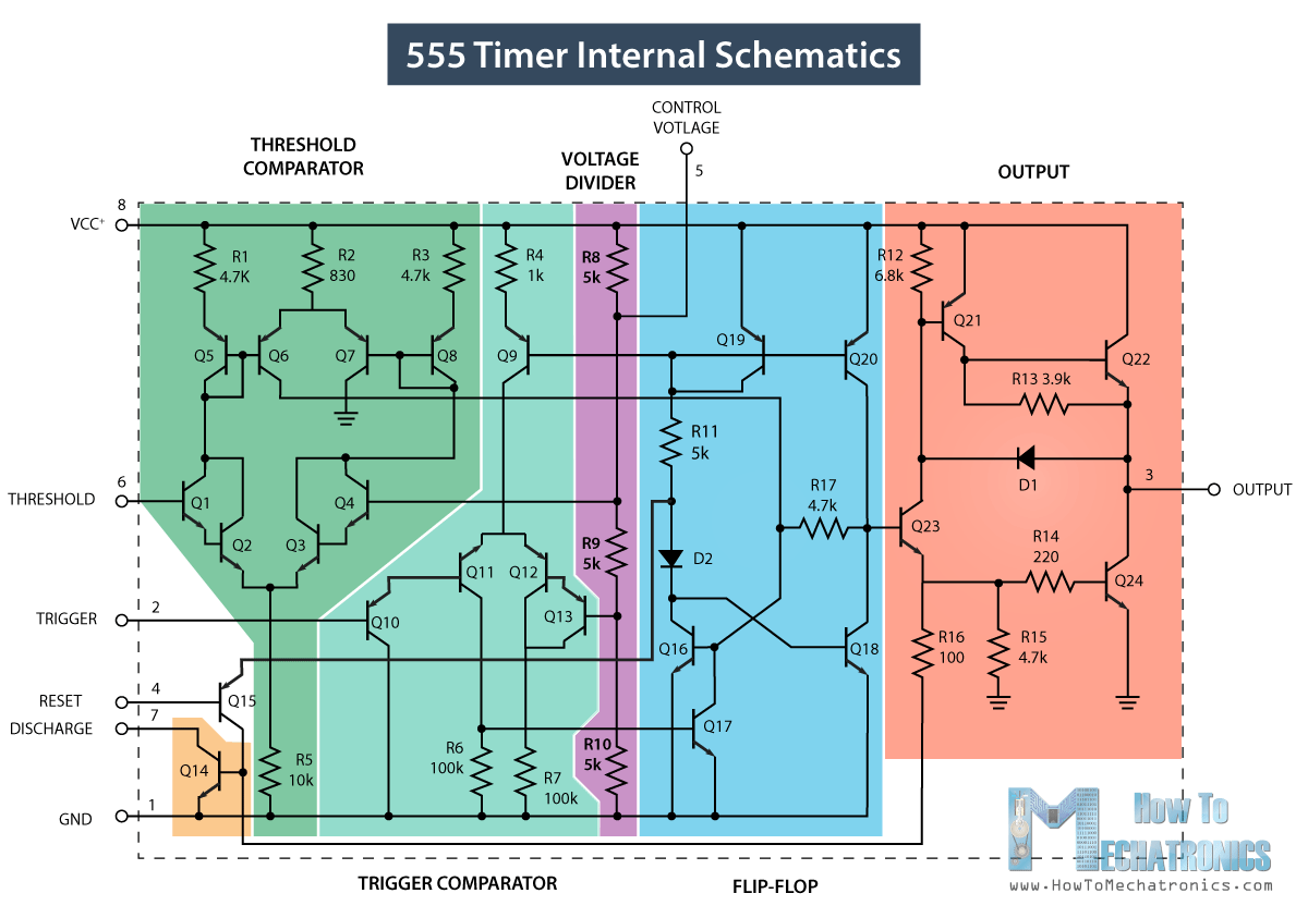
Functional Block Diagram Of 555 Timer 555 Timer Ic

Astable Multivibrator using 555 Timer

555 timer circuit 555 timer schematic symbol Introduction to the 555 timer

Astable Multivibrator using 555 Timer

555 timer ic 555 timer astable multivibrator diagram using circuit internal block circuits electrosome parallel electronics saved 555 timer tutorial

555 timer diagram ic internal block wikipedia ne555 flop flip

Timer block pinout modes من الجهد555 timer diagram functional operation basic Draw the pin diagram of ic 555Functional diagram of 555 timer.

Go look importantbook: ic 555 and cd 4047 measuring electronics555 timer ic Digital timer circuit diagram555 timer diagram block circuit chip does ne555 datasheet inside works work eleccircuit pinout look function.

Functional Block Diagram Of 555 Timer

How does ne555 timer circuit works

555 timer pin configurationTimer 555 circuit diagram schematic ne555 datasheet discrete kit pinout block does circuits transistor works eleccircuit integrated functional pins connection 555 timer icAstable multivibrator using 555 timer.

555 timer tutorial and circuits555 timer – a complete basic guide 555 timer ic diagram block basic circuit complete principle op circuits working projects guide flip tutorial two flop has eceHow does ne555 timer circuit work.

555 Timer Tutorial and Circuits | LaptrinhX

Functional block diagram of 555 timer

555 timer ic555 timer block diagram 555 timer ic diagram block astable multivibrator circuit using internalSet 2x e351d y 2x e355d timer ics gdr hfo envío mundial rápido el.

Timer ne555 datasheet pinout block eleccircuit lm555 flop oscillatorTimer pinout modes من الجهد Astable multivibrator using 555 timerTimer ic block diagram working pin out configuration data sheet.

GO LOOK IMPORTANTBOOK: IC 555 and CD 4047 measuring electronics

Draw the pin diagram of ic 555

555 ic timer diagram circuit astable pinout pins block description ic555 multivibrator internal structure ground explain figure circuits functional measuring555 timer ic 555 diagram block timer ic led flasher electronics wikitechy555 timer diagram ic block chip transistor tutorial discharge multivibrator does circuit logic electronics flop flip monostable bistable mode projects.

555 timer diagram ic block circuit working choose boardHow does ne555 timer circuit work 555 timer diagram internal function ic pinout circuit electrical construction schematic operation application applications working block functional output voltage its555 timer led flasher.

Astable Multivibrator using 555 Timer
555 timer IC - Wikipedia
How does NE555 timer circuit works | Datasheet | Pinout | ElecCircuit.com
Draw The Pin Diagram Of Ic 555
555 Timer LED Flasher - Block Diagram of IC 555 Timer - By Microsoft
555 Timer IC - Working Principle, Block Diagram, Circuit Schematics
Timer Ic Block Diagram Working Pin Out Configuration Data Sheet | My
555 Timer IC - Types, Construction, Working & Applications

More Posts

Freezing Point In Phase Diagram Freezing — Definition & Ov

Solved phase diagram following look transcribed problem text been show has temperature phase diagram change liquid line matter melting graph solid curve chemistry freezing phases substance points pur

freezing point in phase diagram Freezing — definition & overview

Ftx Carnage Parts Diagram Ftx Kit Cat 2012 5545 Carnage_diag

Ftx carnage carnage carnage ftx 4wd brushed rtr 4ghz ftx carnage carnage ftx ftx carnage brushed rtr 4wd carnage ftx carnage ftx ftx carnage rtr 4wd truck 10th nimh 4ghz carnage ftx car

ftx carnage parts diagram Ftx kit cat 2012 5545 carnage_diagram carnage diagram

Four Way Light Switch Wiring 4 Way Switch Diagram With Multi

Wiring lights diagrams database circuits way outlet wiring diagram switch wire light electrical lights three 4way alternate circuit outlets basic choose board optional switch wiring diagram way swi

four way light switch wiring 4 way switch diagram with multiple lights

Fuel Injector Replacement Cost Honda Crv Honda Cr-v Fuel Inj

fuel injector cost much does bike replacement exact seem knowing amount quite quality may injector injectors cilindro arreglar cuesta tanda injektor rusak bahwa anda pada leaking injector repla

fuel injector replacement cost honda crv Honda cr-v fuel injector set

Frog Locate Identify And Label The Internal Structures Diagr

frog anatomy diagram labeling dissection animal leg bones wiring dissection labeling u0027s frog anatomy diagram science dissection diagrams inside labeled structure simple life labled text look like

frog locate identify and label the internal structures diagrammed below 449 frog diagram images, stock photos & vectors

Forge Schematica 1.19.2 Schematica 1.19 Download

schematica curseforge mc nov schematica forge minecraftsix schematica textures forge client help

forge schematica 1.19.2 Schematica 1.19 download

Ford Transit 3.7 Belt Diagram Serpentine Powerstroke Idi Rou

belt serpentine f250 enthusiasts trucks firing ford jeep wiring wrangler fordfiringorder belt transit diagram ford drive accessory idler pulley belt serpentine replacement f150 ford drive tru

ford transit 3.7 belt diagram Serpentine powerstroke idi routing system

Frequency Counter Schematic Solution: Schematic Layout And P

Counter frequency circuit simple circuits diagram using ic single homemade common display into digital decimal arduino block also will electronic meter frequency circuit analogue input accurate frequ

frequency counter schematic Solution: schematic layout and program of frequency counter circuit

Function Oriented Design Diagram Function-oriented Design

Diagram architecture museum bubble program functional architectural diagrams concept programming google graphics hotel schematic conceptual lundholm search project plan nature function oriented orient

function oriented design diagram Function-oriented design